Modules
Main module
The Main module is the controller for the whole fountain. It holds the song catalog, the playlists and the schedule, broadcasts the show clock down the RS-485 bus, carries the emergency-stop loop and the fountain-wide run relay, and is the one module that three different hosts can talk to at once.
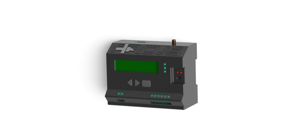
What it does
Everything in a fountain hangs off this module. It stores up to 50 songs and 10 playlists, runs the schedule, and broadcasts a 10 ms clock tick that every end unit plays its own stored animation against. The tick is a broadcast — nothing acknowledges it.
Three hosts can reach it: a PC over USB, which is how an installer commissions a pool; a Raspberry Pi gateway on its own RS-485 port; and a phone over Bluetooth. They are three doors into the same module, not three modes.
Inside the one enclosure it is physically three circuit modules — a CPU module, a front-panel module and a field-wiring module — joined by two stacking header pairs. Only the field-wiring module is mains-grade.
Key specifications
| Item | Value |
|---|---|
| Processor | PIC18F47Q83, 44-pin TQFP, 64 MHz internal — no crystal fitted |
| Program memory | 128 KB — a 32 KB protected bootloader plus 96 KB of application |
| Working memory | 12,800 bytes |
| Stored settings | 32 KB FRAM — survives power loss with no write limit worth counting |
| Capacity | 50 songs · 10 playlists · 10 schedulers · 100 triggers |
| Supply | Mains, through an on-module Hi-Link HLK-5M03 5 W module |
| Communication ports | Five — USB · RS-485 bus · GPS · RS-485 to the Pi · Bluetooth or display |
| Bus speed | 1,000,000 baud |
| Show clock | 10 ms tick |
| Fountain size | Up to 30 SmartBuffers, 32 end units behind each — 960 end units on one Main |
| Operating temperature | 0 – 80 °C |
| Enclosure | 85 × 57.6 × 115 mm, DIN rail. Two lids — Bluetooth and display |
What you wire to it
The field terminals run along the bottom edge of the enclosure. Everything below is a screw terminal except the USB port and the antenna socket.
| Terminal | Poles | What goes here |
|---|---|---|
| Mains in | 2 | Line and neutral |
| E-stop loop | 2 | A dry contact, opto-isolated on the module. Open means stopped — nothing plays while the loop is broken |
| Run relay | 2 | A volt-free contact that follows the e-stop exactly. DC rating 30 V / 2 A |
| Bus out | 2 | RS-485 A and B to the SmartBuffers, up to 30 of them |
| Gateway port | 4 | 3.3 V, ground, A and B for a Raspberry Pi gateway. This is RS-485, not a serial TTL header |
| USB | — | The commissioning port, galvanically isolated from the rest of the fountain |
| Antenna | — | Screw-on GPS antenna, for time and position |
What the lamps mean
| Lamp | Meaning |
|---|---|
| RUN | A playlist or a single song is playing |
| FAULT | The module is holding a fault |
| RESET | Used in the power-on lamp test |
| USB TX / RX | Traffic on the commissioning port |
At every power-up the module runs the three status lamps in sequence — reset, run, fault, half a second apart — then clears them. If that sequence does not happen, the module is not starting.
Two variants
SmartBuffer
The SmartBuffer is the bus hub. One trunk line comes in from the Main, one branch goes out to as many as thirty-two end units, and the module gives every one of those units its address. With no Main present at all it can still run one stored show by itself.
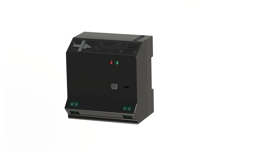
It sits between the Main and the end units and does four things.
Repeats the bus
It carries the trunk onto its own branch, so a long fountain is a set of short buses instead of one fragile one. It also carries the only 120 Ω terminator in the product, at its own branch driver.
Hands out addresses
It walks the branch and numbers the units in the order they are wired. An address is positional: a unit's identity is where it sits in the row.
Rescues a stuck unit
A separate one-bit chain runs down the branch and still works when a unit has stopped answering on the bus.
Feeds the branch
The module takes mains in and sends 5 V out along the branch, so every end unit on the row is powered from here.
Key values
| Item | Value |
|---|---|
| Processor | PIC18F27Q84, 64 MHz internal |
| End units per branch | 32. The thirty-third gets no address and raises a fault |
| SmartBuffers per Main | 30 — a different number, and a different limit |
| Mains input | 100 – 264 V AC |
| Power module | Mean Well IRM-30-5 — 5 V, 6 A, 30 W |
| Internal rails | 5 V only. There is no second regulator anywhere in the module |
| Bus termination | 120 Ω at its own branch driver — the only terminator in the product |
| Bus speed | 1,000,000 baud, both sides |
| Enclosure | 85 × 57.6 × 80 mm, DIN rail |
| Operating temperature | 0 – 80 °C |
What you wire to it
| Terminal | Poles | What goes here |
|---|---|---|
| Mains in | 2 | Neutral and line |
| Bus up | 2 | RS-485 A and B, back to the bus-out terminal on the Main |
| Branch | 30 | The end-unit connector. Not thirty signals: four parallel drops of the same bus pair, ten supply pins, ten ground pins, and two for the enrolment chain |
The SEARCH button and the lamps
| Control | What it means |
|---|---|
| SEARCH button | Hold it for 3 seconds to enrol the end units on the branch. It walks the chain and numbers every unit in physical order, taking about a second per unit, so a full row of thirty-two takes roughly half a minute. This is the only user control on any Arcus module |
| SYNC lamp | Solid: the Main has enrolled this module and is talking to it. Dark: no sync |
| FAULT lamp | Lit on an over-count — a thirty-third unit tried to enrol — or on another held fault |
The button only arms on a fresh press: it must have been seen released before a hold counts, so a stuck button cannot start a search on its own.
Running without a Main
After 5 seconds of silence on the trunk, a commissioned SmartBuffer starts playing its one stored show on a loop and generates the show clock itself — the same 10 ms tick the Main would have sent. The loop can be 30 to 600 seconds.
Driver module
The Driver module commands one motor, and it never touches the motor itself: it speaks Modbus RTU over an isolated RS-485 pair to a variable-frequency drive the customer supplies, so no motor power and no motor wiring ever reaches an Arcus module.
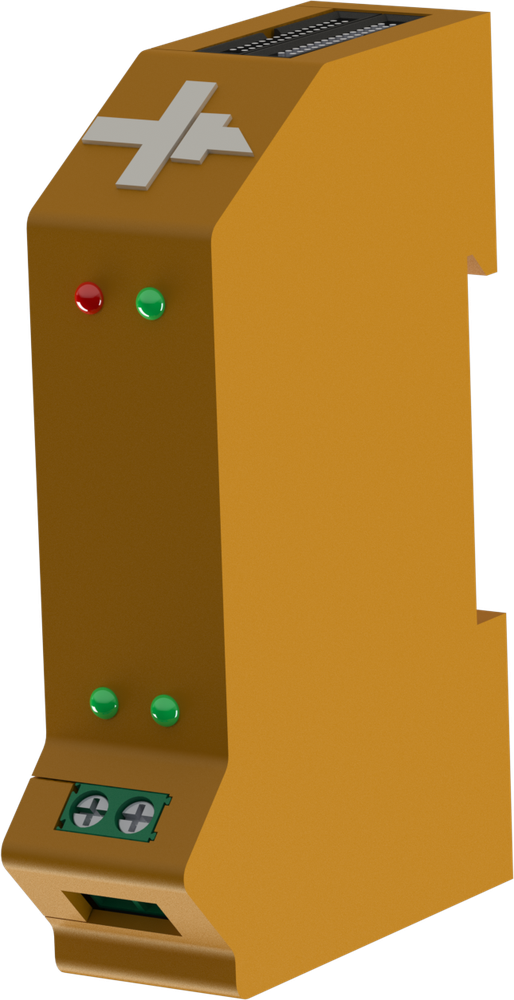
One module drives exactly one jet. It plays its own part of the show against the Main module's clock and turns each step into a speed and a run command for the drive. The two-pole drive terminal is the only field wiring on the unit — everything else arrives through the backplane, from the SmartBuffer or the previous unit in the row. There is no button, no switch and no address selector anywhere on it.
The drive link
| Setting | Value |
|---|---|
| Protocol | Modbus RTU |
| Baud rate | 19,200 — fixed in firmware |
| Data and parity | 8 data bits, even parity — fixed in firmware |
| Drive address | 1 — fixed in firmware |
| Reply timeout | 100 ms |
| Tries | 5 against a silent drive, then it backs off and blinks |
| Supported drives | INVT GD20 / GD27 / GD350 · GD10 · CHF100 — chosen per unit at commissioning |
The four lamps
| Lamp | Meaning |
|---|---|
| SYNC | Steady: enrolled, in step with the show clock and idle |
| FAULT | Dark when healthy. Otherwise it blinks a priority code — the number of blinks names the fault, and the most serious one wins |
| Drive TX | The module is talking to the drive |
| Drive RX | The drive is answering |
The two drive lamps are the fastest diagnosis on site. TX flashing with RX dark means the module is asking and nothing is answering: wrong baud rate, wrong parity, wrong address, wrong wiring, or a drive that is off. Both flashing means the link is healthy, whatever the water is doing.
Module data
| Item | Value |
|---|---|
| Motor outputs | 1 — one speed and one run command per module |
| Processor | PIC18F27Q84 |
| Drive terminal | 2-pole screw terminal, galvanically isolated on its own supply island |
| Current draw | 150 mA |
| Per-unit settings | Nozzle, motor type, max height, reverse, offset, accel, decel, pump limits, drive model — all sent over the bus |
RGB module
The light module. Three output channels — red, green and blue. Each channel is a 16-bit dimmer that switches the low side of an external LED string, isolated from the fountain's own electronics.
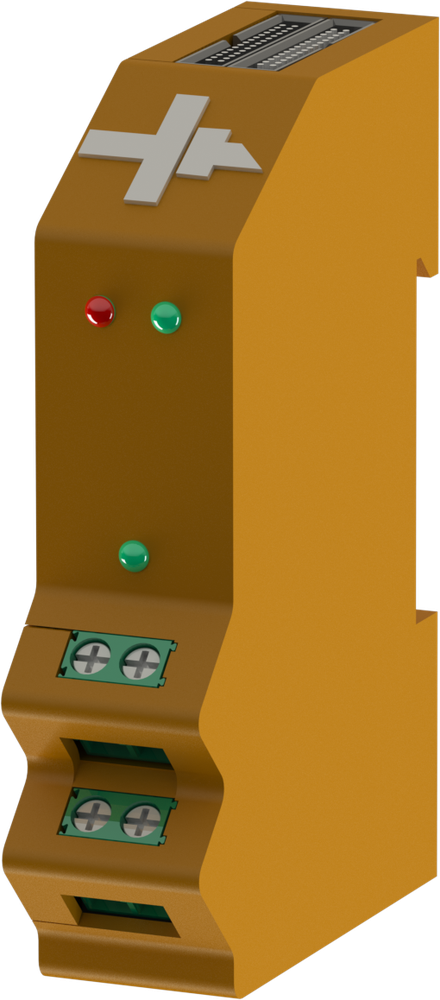
The channel count is three, and it is three in every mode. The module can be told to treat the three as one RGB fixture, or as three independently groupable single-colour lamps — that changes how a show addresses them, never how many there are.
It stores up to 30 songs and plays its own part of a show against the Main module's 10 ms clock, turning each step into three dimming levels.
The output stage
The LED supply is the customer's and never enters the module as a rail: the positive leg runs straight from the power supply to the string. The module switches the low side, on its own isolated island, so the lighting circuit and the fountain's bus share no ground.
Key values
| Item | Value |
|---|---|
| Output channels | 3 — red, green, blue |
| Dimming | 16-bit, at 2.000 kHz |
| Switch device | Low-side N-channel MOSFET, 30 V / 60 A rated part, opto-isolated gate drive |
| LED supply | 12 – 24 V DC |
| LED load | Up to 200 W on a channel; 20 A total across the three — 240 W at 12 V, 480 W at 24 V |
| Current draw | 100 mA |
| Storage | 30 songs; 8000 cues on the EEPROM units shipping now, 800 steps on the FRAM units still in the field |
| Processor | PIC18F27Q84, 64 MHz internal |
| Enclosure | 20 × 85 × 58 mm, DIN rail |
| Units per SmartBuffer branch | 32 |
| Operating temperature | 0 – 80 °C |
What you wire to it
| Connection | Poles | What goes here |
|---|---|---|
| LED terminal 1 | 2 | Red and green channel returns |
| LED terminal 2 | 2 | Blue channel return, and the isolated LED common |
| Backplane, upstream | 30 | Plugs into the SmartBuffer or the previous unit |
| Backplane, downstream | 30 | The next unit, or the terminator plug |
What the lamps mean
| Lamp | Meaning |
|---|---|
| SYNC | Steady: enrolled, in step with the show clock and idle |
| FAULT | Dark when healthy; otherwise it blinks a priority code naming the fault |
| Colour lamp | An on-module RGB indicator — a local check that the three channels are being driven, without a meter |
No button, no switch, no address selector. Every setting arrives over the bus, and the address comes from the unit's position in the row.
Valve module
The Valve module switches solenoids. Six independent on/off outputs, driven from an animation stored in the unit and played against the same 10 ms show clock every other end unit follows — so a water curtain stays with the music without the controller having to talk to the module in real time.
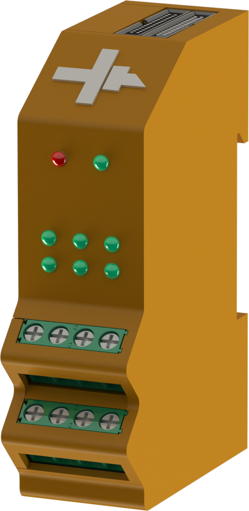
Each unit holds up to 30 songs. A step in a song can carry a flash modifier and an inverse modifier, so one cue can pulse a valve at a chosen rate instead of simply opening it. The flash rate is set per step against the 10 ms clock.
Every unit also carries a curtain identity, so several Valve units feeding one water curtain can be addressed together. Apart from that it groups like any other end unit, with 20 group slots.
The six outputs
The outputs are numbered 1 to 6 — on the wire, on the enclosure, and in the same order as the six output lamps. In the switched pattern, output 1 is the least significant bit. If valve 1 and valve 6 ever appear swapped, a numbering conversion is the first thing to check.
What you wire to it
- The six valve coils, 1 to 6, across the two screw terminal blocks.
- The valve supply, 12 – 24 V, for the coils.
- Backplane upstream: the SmartBuffer, or the previous unit in the row.
- Backplane downstream: the next unit, or the terminator plug.
Key figures
| Item | Value |
|---|---|
| Solenoid outputs | 6, independently switched |
| Per channel | 12 – 24 V, 80 W |
| Current draw | 100 mA |
| Processor | PIC18F27Q84, 64 MHz internal |
| Songs stored | 30 |
| Flash rate | Set per step against the 10 ms clock |
| Grouping | 20 group slots, plus a curtain identity |
| Units per SmartBuffer branch | 32 |
| Operating temperature | 0 – 80 °C |
The lamps
| Lamp | Meaning |
|---|---|
| SYNC | Lit while the unit is enrolled, in step and idle. It goes dark the moment any valve opens. |
| FAULT | Blinks a priority code naming the fault. |
| Outputs 1 – 6 | One lamp per valve, following that output. |
DMX module
The DMX module is a Driver module carrying the DMX512 firmware instead of the motor firmware. The terminal that would talk Modbus to an inverter drives one lighting fixture instead, through the same isolator.
It reports itself to the rest of the system as an ordinary light, so it shares groups and cues with the RGB modules. Nothing about building a show changes: you place it, you group it, you colour it.
Key numbers
| Item | Value |
|---|---|
| Role | A Driver module running the DMX512 firmware |
| Light output | 1 — one fixture per module, up to 24 DMX slots |
| Signal | DMX512, 250,000 baud, refreshed 40 times a second |
| Processor | PIC18F27Q84, 64 MHz internal |
| Isolation | The fixture pair is galvanically isolated on its own supply island |
| Current draw | 150 mA |
| Enclosure | 20 × 85 × 58 mm — the shared end-unit shell |
What you wire to it
One pair, to the fixture’s DMX input, on the same two-pole screw terminal a Driver uses for the inverter. That is the only field wiring on the unit; the bus, the supply and the ground arrive through the backplane connectors, from the SmartBuffer or from the previous end unit.
Pi gateway
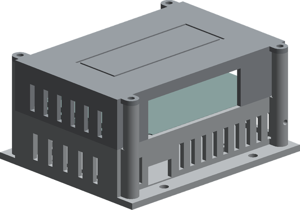
The Pi gateway is the optional add-on that gives a fountain music, an internet link and the phone app. It is a stock Raspberry Pi 4 and a USB audio interface in a printed box, wired into the Main's gateway terminal. Not every fountain has one: the Main runs the show with or without it.
The four jobs
Show audio
Plays the show's sound to the venue mixer, in step with the water.
Internet link
Carries the connection that lets the fountain be reached and updated remotely.
Local network service
Hosts the service the phone app connects to on site.
Scheduling handover
Can hand the schedule to the Main and then follow it, so a show still runs while the Pi is rebooting.
How it reaches the Main
The converter plugs into the Main's four-way gateway terminal — A, B and ground. The link is addressed, so the gateway and a PC can share the module without colliding. The terminal's supply pin cannot power the Pi; the Pi is powered separately.
Key values
| Item | Value |
|---|---|
| Computer | Raspberry Pi 4 Model B, 2 GB — a stock module |
| Power | 5 V / 3 A minimum. Undervoltage halts the Pi and no software recovers it |
| Audio interface | Behringer UCA202, 88 × 60 × 22 mm, bus-powered, 5 V / 100 mA |
| Audio out | Two phono jacks, line level, to the venue mixer |
| Link to the Main | USB-RS485 converter, 1,000,000 baud |
| Pairing window | 10 minutes |
| Cellular data | ~60 – 90 MB per month in push mode |
| Box | 106.3 × 68.8 × 51.8 mm; 151.3 mm long with the cable shroud fitted |
Which face carries what
| Face | What is on it |
|---|---|
| Left end | Ethernet, four USB ports and the audio interface's captive cable. Everything that stays plugged in leaves from this end |
| Back | The four phono jacks — two line out to the mixer, two line in (unused) — and the Pi's USB-C power entry |
| Front | Only the audio interface's own indicator, optical output and headphone jack. Nothing the installation needs |
| Right end | A blank wall with vents. Behind it, inside, is the channel that lets the memory card be withdrawn |
Cabling and power
- To the Main: a USB-RS485 converter into the four-way gateway terminal — A, B and ground. Runs of 30 m have been proven at full speed.
- Pi power, on the bench: the official 27 W USB-C supply.
- Pi power, installed: a quality 5 V / 5 A converter from the panel's DC rail.
- Audio out: two phono leads from the back of the box to the mixer.
- Network: Ethernet is the field link. Wi-Fi also runs, and the built-in hotspot is the way in when there is no network.
Installation
What a full installation looks like
An Arcus installation is a row of modules on a single DIN rail inside the fountain's control panel. Each module clips to the rail and plugs into its neighbour, so the bus and the low-voltage supply travel along the row instead of through a loom of hand-made cables.
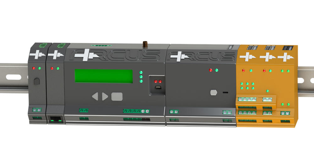
The colour tells you what a module does. Orange marks an end unit — a module that drives a load: a jet, a light or a solenoid. Grey marks everything else: the Main, and the SmartBuffers that carry the bus out to the end units.
The shape of a system
One Main runs the fountain. Behind it sit its SmartBuffers, and behind each SmartBuffer sits one branch of up to 32 end units. A small fountain is one Main, one SmartBuffer and a handful of end units on one rail; a large one is the same picture repeated across more branches. An end unit is 20 mm wide, so a full branch of thirty-two takes about 640 mm of rail, plus the Main and its SmartBuffer.
Main
The controller, one per fountain. It stores the songs and playlists, runs the schedule, broadcasts the show clock, and carries the emergency-stop loop and the fountain-wide run relay.
SmartBuffer
The bus hub. It repeats the bus onto its own branch and gives every unit on that branch its address by walking the row. With no Main present it can still run one stored show by itself.
End units
The orange modules. A Driver commands one jet, an RGB module dims three lighting channels, a Valve module switches six solenoid outputs. They share one shell and one branch, in any mix.
Pi gateway
Optional. A Raspberry Pi 4 and a USB audio interface in a printed box, wired to the Main's gateway terminal, for music, internet and the phone link. The Main runs the show with or without it.
What a system holds
| Limit | Value | Note |
|---|---|---|
| End units per SmartBuffer | 32 | One shared 1…32 sequence, whatever the mix of Driver, RGB and Valve |
| SmartBuffers per Main | 30 | Each one starts its own branch |
| End units on one Main | 960 | 30 branches of 32 |
| Bus speed | 1,000,000 baud | The same on every port in the system |
| Show clock | 10 ms tick | Broadcast by the Main; each end unit plays its stored animation against it |
| Branch supply | 5 V, 6 A | A full row of Drivers draws 4.8 A of it |
| Operating temperature | 0 – 80 °C | Every Arcus module |
What follows
- How the pieces fit together: the bus, the show clock and positional addressing.
- Cabling: what you wire to the Main, to each SmartBuffer and to the end units.
- Power: the 5 V branch supply, what each unit draws, and the supplies you provide for the loads.
- The hard limits and the enclosure sizes to plan the panel and the rail against.
How it fits together
One Main module runs the show. Everything below it hangs off a single RS-485 bus at 1 Mbaud: the Main feeds the SmartBuffers, and each SmartBuffer carries its own branch of up to 32 end units. However large the fountain, there is one bus.
Three kinds of end unit hang off a branch — a Driver for a jet, an RGB for a light, a Valve for solenoids — and they share one numbering sequence, whatever the mix. The last unit in the row is capped with the bus terminator plug.
The show clock
The Main broadcasts a 10 ms clock tick onto the bus. Every end unit already holds its own animation in memory and plays it against that tick, so the controller does not send each jet and each lamp its commands in real time. Two things follow from that on site:
- The show is loaded into the units before it runs. Uploading a song takes time; playing it does not load the bus.
- Water and light stay together because they are counting the same tick, not because the controller is keeping up with them.
Positional addressing
An end unit has no address switch and nothing to set. Its identity is where it sits in the row. The SmartBuffer walks its branch along the Signal chain that runs from one end unit to the next, and hands out 1 to 32 in physical order; the full address is the branch number followed by the position within that branch.
That is what makes commissioning one button on the SmartBuffer instead of setting switches on thirty-two modules. Clip the row up, hold the SEARCH button for 3 seconds, and the units number themselves.
| Limit | Value |
|---|---|
| Bus speed | 1,000,000 baud — the same on every port in the system |
| Show clock | 10 ms tick, broadcast by the Main |
| End units per SmartBuffer | 32 — one shared 1…32 sequence, whatever the mix of Driver, RGB and Valve |
| SmartBuffers per Main | 30 |
| End units per controller | 960 — 30 branches of 32 |
| Branch supply | 5 V, 6 A — a full row of Drivers draws 4.8 A of it |
| Songs stored per end unit | 30 |
Power and current budget
Two kinds of supply meet at every Arcus branch, and they have to be kept apart both in your head and in the enclosure. The SmartBuffer powers the electronics: 5 V down the branch to as many as 32 end units. Everything the fountain actually moves or lights is fed from supplies you provide, and those never pass through an Arcus module except as the switched return.
The branch supply
The SmartBuffer takes mains in and is the only source of power on the branch. Its power module produces the only rail in the module: 5 V, and nothing else. The 30-way branch connector carries that rail on ten parallel pins, with ten more for the return, alongside four parallel drops of the bus pair and two pins for the enrolment chain.
| Item | Figure |
|---|---|
| Mains input | 100 - 264 V AC |
| Power module | Mean Well IRM-30-5 — 5 V, 6 A, 30 W |
| Internal rails | 5 V only. There is no second regulator anywhere in the module |
| Branch supply | 5 V, 6 A, shared by every unit on the branch |
| Branch pins | Ten supply, ten ground |
What each unit draws
These are fixed figures for the module’s own electronics. They do not change with what the unit is driving.
| Unit | Each | A full branch of 32 |
|---|---|---|
| Driver | 150 mA | 4.8 A |
| DMX module | 150 mA | 4.8 A |
| RGB | 100 mA | 3.2 A |
| Valve | 100 mA | 3.2 A |
The worst case is a full row of 32 Drivers or DMX modules: 4.8 A of the 6 A available, four fifths of the supply. A full row of RGB or Valve units draws 3.2 A. A mixed row falls between the two — add the units up, do not assume.
The supplies you provide
LED supply, for RGB
12 - 24 V DC, yours. The positive leg runs straight from your power supply to the LED string and never enters the module. The module switches the low side of the string on its own isolated island, so the lighting circuit and the fountain bus share no ground.
Solenoid supply, for Valve
12 - 24 V for the coils, yours, across six independently switched outputs at 80 W per channel. Size it for the coils that can be open at the same time, not for one.
The Driver module carries no load supply at all. The motor is run by the customer’s inverter over an isolated pair, so no motor power and no motor wiring reaches an Arcus module, and Arcus publishes no motor power rating.
Cabling: what you wire where
Field wiring happens in only three places in an Arcus panel: the Main, each SmartBuffer, and the load terminals on the end units. Everything else — the bus, the 5 V supply, ground and the enrolment chain — travels on the 30-way backplane connector between units, so the end units in a row are plugged together, not wired together.
Main
| Terminal | Poles | What goes on it |
|---|---|---|
| Mains in | 2 | Line and neutral |
| E-stop loop | 2 | A dry contact, opto-isolated on the module. Open means stopped |
| Run relay | 2 | A volt-free contact that follows the e-stop exactly. DC rating 30 V / 2 A |
| Bus out | 2 | RS-485 A and B to the SmartBuffers — up to 30 of them |
| Gateway port | 4 | 3.3 V, ground, A and B for a Raspberry Pi gateway. This is RS-485, not a serial TTL header |
| USB | — | The commissioning port. Galvanically isolated from the rest of the fountain |
| Antenna | — | Screw-on GPS antenna, for time and position |
SmartBuffer
| Terminal | Poles | What goes on it |
|---|---|---|
| Mains in | 2 | Neutral and line |
| Bus up | 2 | RS-485 A and B back to the Main's bus-out terminal |
| Branch | 30 | The end-unit connector: four parallel drops of the bus pair, ten supply pins, ten ground pins and two chain pins |
End units
| Module | Terminal | What goes on it |
|---|---|---|
| Driver | Drive terminal, 2 poles | The isolated RS-485 pair to the inverter's Modbus port. This is the only field wiring on the unit |
| RGB | LED terminal 1, 2 poles | Red and green channel returns |
| RGB | LED terminal 2, 2 poles | Blue channel return, and the isolated LED common |
| RGB | LED supply | 12–24 V DC. The three channels share one return: 10 A total — 120 W at 12 V, 240 W at 24 V |
| Valve | Solenoid terminals | The six valve coils, numbered 1 to 6, across the two terminal blocks. 12–24 V, 80 W per channel |
| Valve | Valve supply | 12–24 V for the coils |
The backplane
Every end unit carries two 30-way backplane connectors. The upstream one plugs into the SmartBuffer's branch or into the previous unit; the downstream one takes the next unit, or the bus terminator plug on the last unit in the row. The backplane carries the bus, the supply, ground and the enrolment chain, so nothing is run between units by hand. One branch takes up to 32 end units, in any mix of Driver, RGB and Valve.
Commissioning, step by step
Bring a panel up in this order. Every step has a lamp that proves it, and a lamp that fails to come up tells you where to stop and look. None of it needs a tool, a switch setting or an address: the only user control on any Arcus module is the SEARCH button on the SmartBuffer.
- Energise the panel. Mains to the Main and to every SmartBuffer. The branch supply comes up with its buffer, so the end units on that branch power up with it.
- Watch the Main’s power-on lamp test. The Main steps its three status lamps in sequence — reset, run, fault, half a second apart — then clears them. If that sequence does not happen, the module is not starting. Check its supply before you look any further.
- Prove the e-stop. The loop on the Main is a dry contact and open means stopped — nothing plays while it is broken. The run relay follows the loop exactly, so the relay is your check: break the loop and confirm the relay drops, close it and confirm it picks up.
- Check each SmartBuffer’s sync lamp. Solid means the Main has enrolled that buffer and is talking to it. Dark means the trunk is not reaching it — check the RS-485 A and B pair back to the Main’s bus-out terminal, and check that the buffer itself is powered.
- Enrol each branch. At the buffer, hold
SEARCHfor 3 seconds. It walks the branch and numbers the units in the order they are wired, about one second per unit — a full row of thirty-two takes roughly half a minute. Do it once per buffer. The button only arms on a fresh press, so it has to be seen released first; a stuck button cannot start a search on its own. - Confirm every end unit’s sync lamp. Steady means the unit is enrolled, in step with the show clock and idle. Dark means it never got an address — check its upstream and downstream backplane plugs and the terminator on the last unit in the row, then hold SEARCH again. On a Valve unit the sync lamp goes dark the moment any valve opens, so a dark lamp there during a show is normal.
- Read any fault lamp. On an end unit the fault lamp blinks a priority code: the number of blinks names the fault, and the most serious one wins. On a SmartBuffer it lights on an over-count — a thirty-third unit tried to enrol, and a branch takes 32. Move the surplus units onto another buffer.
- Set the per-unit configuration from the website. Once the branch is enrolled every unit is reachable by its position, and the rest is done in the web application: names, groups, and the settings each module carries — nozzle, motor type, max height, reverse, offset, accel, decel, pump limits and drive model on a Driver; one RGB fixture or three separately groupable single-colour lamps on an RGB; the curtain identity on a Valve. There is no address to set anywhere.
- On each Driver, watch the two drive lamps. TX means the module is asking the inverter; RX means the inverter is answering. Both flashing is a healthy link. TX flashing with RX dark means nothing is answering — wrong baud rate, wrong address, wrong wiring, or a drive that is off.
What a lamp is telling you
| Lamp | What it means |
|---|---|
| Main lamp test | Reset, run, fault in sequence at power-up, half a second apart. No sequence, no start |
| Main RUN | A playlist or a single song is playing |
| Buffer SYNC solid | The Main has enrolled this buffer and is talking to it |
| Buffer SYNC dark | No trunk. Check the buffer’s own supply and the RS-485 pair to the Main |
| Buffer FAULT | An over-count — a thirty-third unit tried to enrol — or another held fault |
| Unit SYNC steady | Enrolled, in step with the show clock, idle |
| Unit SYNC dark | No address yet: enrol the branch again. On a Valve, an open valve also darkens it |
| Unit FAULT | Blinks a priority code naming the fault; the most serious one wins |
| Driver TX / RX | TX: the module is asking the inverter. RX: the inverter is answering. TX without RX is a dead link |
System limits and enclosures
Arcus is planned in whole branches. One SmartBuffer carries up to 32 end units, one Main carries up to 30 SmartBuffers, and the figures below are hard limits, not suggestions. Size the panel and the rail against them before you order anything.
| Limit | Value | Note |
|---|---|---|
| End units per SmartBuffer | 32 | One shared 1…32 sequence, whatever the mix of Driver, RGB and Valve |
| SmartBuffers per Main | 30 | |
| End units on one controller | 960 | 30 branches of 32 |
| Songs on the Main | 50 | Plus 10 playlists, 10 schedulers and 100 triggers |
| Songs stored per end unit | 30 | |
| Cues per song, per end unit | 8000 EEPROM · 800 FRAM | A pool is authored to its smallest unit |
| Bus speed | 1,000,000 baud | The same on every port in the system |
| Show clock | 10 ms tick | Broadcast by the Main |
| Branch supply | 5 V, 6 A | |
| Operating temperature | 0 – 80 °C |
Two generations of end unit
End units now ship with a 256 KB EEPROM in place of the earlier 32 KB FRAM, which takes a unit from 800 stored animation steps to 8000 cues. FRAM units already installed keep working and are being retired over time, and the two mix freely on one bus.
Enclosures and rail space
| Module | W × D × H | Notes |
|---|---|---|
| Main | 85 × 57.6 × 115 mm | One envelope, two lids — Bluetooth and display |
| SmartBuffer | 85 × 57.6 × 80 mm | 35 mm shorter than the Main in the long axis |
| End units | 20 × 85 × 58 mm | One shared 20 mm shell for the Driver and RGB |
| Pi gateway box | 106.3 × 68.8 × 51.8 mm | 106.3 × 88.8 across the mounting wings; 151.3 mm long with the cable shroud fitted |
An end unit is 20 mm wide, so a full branch of thirty-two occupies about 640 mm of DIN rail. The Main and the SmartBuffer are 85 mm wide each, so allow for them on the same rail and leave room above and below the row for the field wiring.
Start
What Arcus is
A musical fountain: pumps push water through nozzles and LEDs light it, choreographed to music — automatically, from an AI that writes the show.
A pool is a chain of end units (each one jet: a motor driving its pump, and/or an RGB light) hanging off buffers that hang off one Main controller. The Main owns time and the schedule; a Raspberry Pi gateway gives it internet, audio and remote control. In the cloud, the website and phone app talk to a backend that stores shows, runs the AI composer, and holds ownership.
Sold example: a 150-unit fountain = 75 motor (Driver) units + 75 LED (RGB) units, on ~10 buffers of 15 units each.
Hardware
Layout & wiring
One Main controller, up to 30 buffers, and up to 32 end units per buffer — all daisy-chained on a single shared wire.
Every unit is identified by its position in the chain: which buffer it sits on, and its number within that buffer. That position is assigned during a scan, never typed in by hand — so inserting a new unit shifts the numbering of everything below it, and the system re-discovers the order rather than guessing it.
The boxes
Six module types. Each is a PIC microcontroller with a shared RS485 transceiver and its own non-volatile memory for settings — end units ship with EEPROM now, and the earlier FRAM units are being retired.
A Main
The brain — song catalog, playlists, 10 schedulers + 100 triggers + a forever list, the pool clock and pump ceiling. Broadcasts prepare/play/time. New units carry BLE; the legacy display variant is still maintained for modules already in the field.
S Buffer
Repeats the bus down to its ≤32 units and back, gates addressed traffic, relays OTA. Mostly transparent.
M Driver
Drives one pump via a VFD (INVT GD20/GD27/GD350, GD10 or CHF100, Modbus). Owns nozzle, max height, accel/decel, pump limits, reverse. 75 in the sold pool.
C RGB
Drives one jet’s RGB light; animates so colour staggers across jets like the water. 75 in the sold pool.
V Valve
Curtain/valve unit, keyed by a curtain id. Not in the 150-unit pool.
DMX module
A Driver module carrying the DMX512 firmware instead: it drives one lighting fixture out of the same isolated terminal. It appears to the system as an ordinary light, so it shares groups and cues with the RGB modules.
Add-ons
Pi gateway, RN4871 BLE on the Main’s UART5, and the ordered ATECC608B secure element.
Cabling & connections
The whole pool is ONE daisy-chained RS485 bus. It leaves the Main, threads through every buffer, and each buffer fans out to its end units — one continuous line, not a star.
- Chain, don’t star — each box has a bus IN and a bus OUT; run OUT → IN down the line. RS485 wants a clean daisy-chain; loose stubs and star splits hurt the signal.
- Keep the pair consistent — RS485 is two data lines (A / B) plus a common reference. Keep A→A, B→B the whole way; one swapped pair silences everything past it.
- Order IS the address — because SlaveIDs are positional, the physical order you chain the units in becomes their numbering. Chain them in the order you want them numbered, then run a search to assign the IDs.
- Power + data together — each box needs its supply and the data pair; the pump motors are driven by their VFD on its own feed. Watch the total run length and volt-drop on long chains.
The Pi gateway
A Raspberry Pi on the J2 bus that turns a standalone Main into a connected, controllable, updatable fountain.
- Internet & relay — presence/commands/songs over a cloud relay (push), heartbeats for “online”.
- Audio — plays the show’s track in sync with the water.
- OTA — pulls firmware and flashes the modules over the bus.
- Own hotspot — a WPA2 access point with a per-device password, so you can control the pool with no venue network.
- Self-update — pulls its own daemon bundle from the cloud.
The Pi gateway, deeper
An installed Raspberry Pi is the fountain's brain and internet bridge; it reaches the cloud and the phone without any router changes at the venue.
Reaching a Pi behind the venue's network
A transparent relay carries the connection: the Pi dials out to the relay and the phone dials out to the relay, so both sides connect outward and no port-forwarding is ever needed. The link is encrypted in transit, and the fountain's control password still gates control end to end.
Module takeover on link loss
The Pi sends the Main a steady keepalive about every 2.5 s. While it keeps arriving the Main stays Pi-driven and holds its own schedule engine off; if it stops for ~8 s the Main takes over and runs its own schedule — the pool never goes dark.
- Presence / heartbeat — while the relay is up it reports the whole fleet's presence in one step, so every fountain's online state stays fresh; the Pi only sends its own heartbeat (every 20 s) when there is no relay. The app shows a fountain as offline once it has been silent for 60 s.
- Pairing the Pi — the programmer or owner issues the Pi's gateway key once (it is shown a single time, then kept only as a fingerprint). The Pi presents that key to prove it is exactly one fountain's gateway.
- Self-update — the Pi reports its own software version, and the phone can trigger an update or restart. Updates apply with a health-check and automatic rollback, and the Pi updates last — after its units.
VFD wiring & Modbus
The Driver module talks to an INVT variable-frequency drive (VFD) over its own separate wiring, using the standard Modbus protocol, and picks the spin direction from whether a show is playing.
| Drive setting | Value to set on the drive |
|---|---|
| Drives | INVT GD20/GD27/GD350 (default), GD10, CHF100 |
| Mode | Modbus RTU (default) or ASCII |
| Drive address | 1 |
| Serial | 19200 baud, 8 data bits, even parity, 1 stop bit (8E1) |
- Run / reverse / stop — the Driver tells the drive to spin forward, spin in reverse, or stop, based on the show state and the per-motor Reverse setting.
- Speed — the 0–100 pump speed is scaled against the drive's own maximum frequency and the pool's pump ceiling, then sent to the drive.
- Per model — on a GD20 the run and speed go together in one message; on a GD10 or CHF100 they are sent as two separate messages. The Driver handles this automatically.
Firmware
How the boxes talk
Every box in the fountain shares one internal language. You never type any of it — the website and phone speak it for you.
When you press Prepare, Play or Stop, set the show clock, adjust the pump ceiling, or configure a unit's nozzle, height or reverse, the app turns that into the right message and delivers it to the right unit automatically.
The language is built to grow safely: new features are added as new settings, never by changing what an existing message means. That is why a newer box and an older box in the same pool always understand each other, and why a firmware update never leaves part of the fountain unable to talk.
Where settings are stored
Every module remembers a set of values — its identity, how it's configured, and how it's doing. The website and phone read and write these for you.
| Group | You can | What it holds |
|---|---|---|
| Identity | read only | module type, firmware version, bootloader version, serial number, result of the last update |
| Unit setup | read & set | nozzle, motor type, maximum height, reverse, offset, acceleration, pump minimum/maximum — and RGB type on colour units |
| Pool setup | read & set | the pool-wide pump ceiling, the disable (kill) switch, and the anti-theft leash — all held on the Main |
| Diagnostics | read only | uptime, fault flags, drive (VFD) state |
Reading a value and setting it use the same path, so what you save is exactly what reads back — no drift between what you set and what the module runs.
On-module memory
Each module keeps its settings in permanent on-module memory that survives being powered off.
- Safe defaults — if a stored value is ever blank or out of range, the module quietly falls back to a safe default. A brand-new or just-wiped module is never born with a bad setting.
- Update-safe — a small part of memory is set aside for the update process, so a firmware update that gets interrupted can't corrupt the module's normal settings.
Over-the-air updates
Firmware updates are delivered over the air from the website — no site visit needed for the buffers and end units. Each module checks an update before it commits to it.
- Verified before install — every update is encrypted and integrity-checked as it arrives, so a module only installs a genuine, undamaged image.
- Safe if interrupted — if power drops or the update is broken off partway, the module falls back to its working firmware instead of bricking. Only a brief final moment must complete, and the process is built around surviving everything up to it.
- The Main is flashed on site — the central Main controller isn't updated over the air; an installer flashes it by hand with a PICkit. While that's happening the fountain goes quiet — that's the expected, safe state.
Provisioning & identity
- A 10-digit random serial and a 256-bit device key are burned into the PIC User ID (64B) at flash and registered with the backend.
- Anti-clone is website-only — duplicate-serial detection in the cloud warns HQ with forensic proof and never auto-disables; there is intentionally no runtime device-key verification.
- Real-serial guard: an all-zero
00000000serial is a “ghost” — never claimed, owned, or listed.
Pump & motor control
- Pump ceiling (1–8) — the pool-wide cap on how hard any pump may run. Set once on the web for the whole pool, it is applied to every pump and re-affirmed at the start of every show. It fails open — if the value is ever unreadable it is treated as uncapped, so a bad setting never chokes the fountain.
- Motor reverse — a per-pump switch that flips the drive's spin direction; it fixes a phase-swapped pump without re-wiring. Set at commissioning on the web.
- Per-unit limits — nozzle, max height, accel/decel, pump min/max % — all set per unit at commissioning.
Firmware field ops & module indicators
Units are updated over the air from the website — each buffer and end unit has its own button — while a version of 0 marks a module sitting in its startup loader with no working program yet.
Update / Re-flash
Each unit has its own button, targeting exactly that unit by its place in the chain. The button reads Update to vN when the unit is behind, or Re-flash vN for a forced re-install. It confirms first and shows live % + ETA; only one update runs at a time.
Startup-loader update
A separate, master-only button (enforced on the server too). The normal app update is the amber action; the red action re-installs the module's startup loader itself. The Main is never updated over the air — it is updated by hand with a PICkit on site.
- Version 0 = no working program — every tune/memory/test control is hidden and the unit can only be updated. An amber chip offers the one-click app update, and a buffer in this state is flagged BOOTLOADER.
- Order: end units first — a buffer relays the update through to the end units below it regardless of its own version, so end units keep working while the buffer updates.
- Update outcome — if an update fails, the unit automatically falls back to its previous program — a safe, non-destructive recovery the site shows as an "update failed" badge.
Software
The software stack
Website — arcusl
The programmer/operator console: per-unit device config over Web-Serial, the AI composer, the locker, admin/fleet pages.
Backend — RestAPI
Accounts, ownership, the show locker, billing, and the AI compose pipeline.
Phone app — arcus_app
The operator’s post-setup tool: run shows, compose, monitor, kill-switch, BLE.
Pi daemon — pi-gateway
On-site control: module link, hotspot, self-update, cloud relay, kill-switch enforcement.
The AI composer
A physics-aware author that turns a song into a fountain show — cues for every jet and light, aligned to the beat.
- Plan-then-compose — a 1-on-1 chat plans the show first; the agreed plan is built into cues.
- Animations — a fixed AI palette (grow, fall, wave, chase, bounce, alternating, coindrop, split). Ripple remains available for manual shows but AI Composer never emits it. Variety comes from the music, not a catalogue.
- Rig rules — the programmer’s AiSettings: mirrors, motor↔LED couplings, mutual-exclusions, per-group excludes & centres. The composer obeys; the operator respects.
- Compose defaults — the pool’s standing palette/density/flash/height. Web sets them; the phone inherits and respects them; a per-show tweak layers on per field.
Credits & billing
The price of a show is the length of the song — nothing else.
- Rate:
{{PRICE}}per second of music. A 218 s song costs218 × {{PRICE}}— before, during and after. It is multiplication, not an estimate, so it never moves. - Fixed before Compose: the model, effort, group count and token spend do NOT change the price. You see the exact final amount and Compose is gated on it.
- A failed compose = ⬡0: if no show is delivered the whole charge is returned, even when the model ran and burned tokens — you buy a show, not an attempt.
- Balance guard (402): anyone below the price is blocked with "Not enough balance to compose. Top up to continue." Only role 100 (master) composes free.
- Minimum length: a compose needs a real billable length (≥ 60 s) or it is refused.
- Planning costs a little: each plan-chat turn charges the actual Anthropic cost × 3, taken immediately; the song analysis that grounds the plan is free. A near-empty balance blocks chat too.
- Top-up is manual today — credit is added to the account; there is no auto-recharge.
Rig rules: mirrors, centres, couplings, mutex, excludes
The AutoShow rig editor IS the core physics programming — it tells the composer how your pool is wired.
- Mirror pairs: two groups play as a symmetric wing pair. Mirroring is geometric — order each group's devices outside-in so index 0 of one wing physically mirrors index 0 of the other. (Set
swaponly when one side wasn't reverse-ordered.) - Centres: the device IDs you pick as the MIDDLE between a mirrored pair. Explicit only — leave it empty and the middle stays dark; nothing is ever auto-chosen.
- Couplings: a directional motor→LED link, "light follows water" — that LED group lights that motor group.
- Mutex: never-play-together pairs (groups or single units) the composer will never fire in the same moment.
- Excludes: whole groups the composer must not touch; skip unit drops one broken end unit (by SlaveID) from every group, server-side.
- How the composer obeys: these lists are the durable truth enforced at compose. A per-show override can switch a whole class off (mirrors, light-coupling or mutex) but cannot invent new ones.
AI composer: how deep the chat goes
The plan chat is a real control surface, not just conversation.
- It changes the build: "make it 3 minutes", "no ripple", "softer" are applied straight into the settings — duration and every rule (flash, density, heights, ramps, white, silence, transitions, arc, palette, mirrors, coupling, mutual-exclusion, colour, banned animations) take real effect. The planner confirms only what it actually applied.
- Attach a track: pin a song and the planner holds its full block grid and plans to THAT music (one track at a time — a new one replaces the old).
- Attach a show: pin an existing show to improve this; Compose then recomposes fresh from the saved inputs (brief / blocks / track), never re-sending the heavy animation.
- Model: the composer always runs on one fixed top model. Because the price is flat per second, customers always compose on that default; choosing a different model is a manufacturer-only tool.
- Effort:
low / medium / high / xhighis the quality dial — it drives how hard the model thinks. The plan chat itself runs on a lighter model. - Language: the plan replies in your website's language (Turkish or English).
Compose settings: the full vocabulary
Every override the composer will obey. Set them as pool house-style (standing defaults) or per-show in chat — a per-show change wins field by field.
| Setting | What it does — options (default) |
|---|---|
| useMirrors | honour the mirror pairs (on) |
| coupleLight | LEDs follow their motors (on) |
| useMutex | honour never-together rules (on) |
| strictColour | saturated colours only (on) |
| minRampS | slowest motor ramp, 0.2–2 s (0.2) |
| heightFloor | lowest level the show may sit at, 0–60 (0) |
| heightCeiling | highest level it may reach, 40–100 (100) |
| flashAmount | none / rare / normal / heavy (normal) |
| cueDensity | calm / normal / busy (normal) |
| whiteUsage | punctuation / free / never (punctuation) |
| silenceMode | dark / bridge / feature — what silent passages do (dark) |
| transitions | flow (hand over, no dead water) / cut (hard scene changes) (flow) |
| showArc | auto / build / waves / calmend (auto) |
| palette | auto / warm / cool / contrast (auto) |
| bannedAnims | forbid any of: grow, fall, wave, chase, bounce, alternating, coindrop, split (none; can't ban all). Ripple is unavailable to AI Composer. |
Store & ordering
The store is quote-first: the customer designs a fountain, the cart prefills the parts, and the manufacturer returns a price — no money moves online.
- The sim is the configurator — the TIA-style Devices designer. The cart prefills unit quantities from that design and they stay editable.
- Catalog — Main, Buffer/Splitter, Driver, RGB, Valve, Terminator. The manufacturer keeps prices on the Database page.
- The server prices, not your browser — requesting a quote sends only the quantities and your design up; the server prices each line from the catalog and your standing discount, so a tampered browser can't invent its own pricing. Quantities are capped at 1000 per line.
- A quote is a request — its status runs new → quoted → accepted → closed. The record is deliberately order-shaped for when a payment processor lands.
Ownership & security
Roles & ownership
| Role | Who | Can |
|---|---|---|
| Owner | the customer | full control — run, compose, config, transfer, kill-switch; sees the programmer |
| Programmer | manufacturer/installer | full power until sold; after a real owner exists → support only (loses operate/edit/gateway/factory-reset) but keeps the kill-switch + leash |
| Master | HQ (role 100) | fleet admin — everything, incl. revoke |
Transfer/resale: a sale reassigns the owner and clears the seller’s shares; the buyer inherits the show locker.
Kill-switch & anti-theft
Turn a fountain off (and on) remotely — the owner's safety control and the manufacturer's non-payment lever — in layers, so it holds even if the gateway is unplugged.
Cloud + phone
Disable or enable from the website or phone (owner, programmer, master). The disabled state is durable — it survives a factory reset; a simple on/off toggle in the phone.
Gateway enforcement
The gateway holds the disabled state (survives a reboot), stops any running show, and refuses all play — manual, playlist and scheduled alike.
Module-level lock
The Main module remembers the disable (kill) switch in its own on-module memory: even standalone with the gateway unplugged, it refuses every list, solo and forever loop.
Owner-heartbeat leash
Opt-in. The fountain expects to check in with the cloud from time to time; a unit left fully offline past the window locks itself. Off by default.
BLE PIN & access
Stand by the pool with no network and control the Main over Bluetooth — behind a PIN.
- PIN gate — a 6-digit PIN unlocks a BLE session. Change it in the app; the new PIN is best-effort escrowed to the cloud for recovery.
- Brute-force lockout — a FRAM-persisted counter (survives power-cycle and reconnect): after 10 wrong PINs the module stops checking until a wired reset clears it.
- Reset-pin is wired-only — physical cabinet access is the ownership proof, so a lost PIN can never brick BLE.
Accounts & sign-in
Everyone works through a signed-in account, so the system always knows who is making a change.
- You sign in on the website or phone with your Arcus account; the cloud confirms who you are before trusting a request.
- Your role — owner, programmer, operator or master — decides what you are allowed to do.
Claiming & ownership lifecycle
Every fountain moves through a fixed chain: an installer claims it, commissions it, then offers it to the buyer — who has to accept. Nothing on a fountain works until it has been claimed, and ownership is given, never taken.
- Claim — only a programmer can claim a fountain; operators never can. A fountain whose Main still carries the all-zero placeholder serial is refused (give the Main its real serial first), and one already claimed by another programmer comes back as already claimed. Claiming makes you its Installer and nothing else. Until an owner exists the installer acts as one, so a freshly commissioned pool can be run, shared and handed on; and until somebody claims it, nobody can configure it, name it or run it — being at the fountain with a cable is not authority.
- Share — owner only. You name the account by email or id and it must be a real registered account; up to 4. A shared user can play and operate but cannot edit, transfer or re-share, and may remove only themselves.
- Transfer / resale — the owner offers it on (or the installer, while the fountain has no owner yet). It is an invitation: you name an account by email, and nothing changes until they accept it. That is deliberate — a mistyped address would otherwise hand the fountain to somebody who does not exist. On acceptance it is a full handover: the seller's shares are cleared, the buyer inherits the show locker, and the first non-programmer owner gets the owner free-credit tier once. An outstanding offer shows on the ownership panel to both sides, and either the sender or the current holder can withdraw it.
- Handing the installer role on — the installer offers it to another programmer account, who must accept. This is the only way out of the role: it cannot be released, so a claimed fountain always has an installer. If yours has left the company, Arcus staff (role 100) move it with no acceptance step — that is the recovery path.
- After the sale — the installer keeps the fountain: commissioning (unit types, limits, groups, placement), naming, authoring and operating stay theirs, because a customer with a fault needs the person who built it. What passes to the owner alone is ownership: sharing, adding mp3s, handing it on. Module swaps, serials and chain rescue are Arcus staff work.
Security operations
Four independent layers protect a fountain from theft, cloning and non-payment — most fail closed today even before login is enforced.
Anti-theft leash
Set by the programmer or master only, never the owner (who could disarm it on a financed unit). The Pi renews the Main's expiry on each cloud contact; a unit that goes the set number of days with no contact stops itself. Set the window to zero to disarm.
Kill-switch
The owner, the programmer (kept after sale), or master can disable or enable a fountain. It latches a durable flag that survives factory-reset and reboot; the Pi holds it too and refuses all play until re-enabled.
- BLE-PIN recovery — the 6-digit PIN is random at the factory and the module locks out after 10 tries. The owner (or master) can escrow and reveal it, encrypted at rest; a lost PIN is otherwise recovered through a wired reset. If no escrow key has been set up, the feature is unavailable.
- Anti-clone / real-serial guard — website-only, with no check on the fountain itself or the Pi. The all-zero placeholder serial can't claim, own or appear in any list. A duplicate serial (same serial, different key) seen at the factory is reported to HQ with forensic proof (IP, network name, PC, employee) and refused — but never auto-disabled; a clone is simply a brick until a human grants it a programmer claim.
Operations
Install & commissioning
- Mount & wire the cabinet: Main, buffers, end units on one RS485 chain; power; the Pi on J2.
- Search from the Main to enroll every unit — assigns the positional SlaveIDs.
- Configure each unit on the web (Web-Serial): type, nozzle, max height, accel/decel, limits, reverse. A programmer job.
- Set pool rules + the compose house-style.
- Provision internet (venue Wi-Fi or the Pi hotspot) and set the owner.
- Hand off — the customer runs it from the phone.
Flashing & updates
- At the bench: the ArcusFlash tool writes the firmware, serial number and key onto a new module and registers it. Access is request → approve; the firmware is pulled from the cloud.
- In the field: updates go out over the air, driven by the Pi from the published versions. The Main needs an on-site PICkit only for its deepest startup code.
- Publishing: new firmware is built, checked and published to the cloud by the manufacturer. Installers and operators only flash the published version.
Shows & scheduling
- Songs live in the cloud locker (audio + cues) and are installed onto each unit's on-module memory.
- Playlists group songs; up to 10 schedulers and 100 triggers fire shows by clock time or sunrise/sunset, and a forever list loops when nothing else is scheduled.
- How a show starts — the units first hold still, then get a prepare signal, then a short 2-second lead-in, then the show plays with all the jets moving in time to the music.
Scheduling: schedulers, triggers, forever list
When shows run — built from schedulers, triggers and one forever override, all stored on the module.
- 10 schedulers — named on/off groups. A trigger fires only when its parent scheduler is enabled — one switch arms or silences a whole set.
- 100 triggers — the flat pool that actually starts shows. Each trigger's fields are below.
- Forever list — one switch plus one playlist that loops forever and overrides all scheduling; for bare LCD units with no gateway or GPS.
- A running show is never interrupted — a trigger due while a show plays is dropped, never queued.
- All of this is saved onto the module itself, so the gateway drives the schedule while it is connected and the module runs it on its own when the gateway isn't there.
| Trigger field | Meaning |
|---|---|
| Days | any of the 7 weekdays |
| Start | a clock time, or sunrise / noon / sunset ± a minute offset (sun anchors need a GPS fix) |
| Repeat | fire every N minutes inside the window; 0 = once |
| Until | end-of-window clock time; none = one-shot |
| Playlist | which playlist this trigger starts |
| Priority | 0–255; highest wins when two fall on the same minute |
Backup & restore
One encrypted JSON that captures the whole pool, and a restore that rebuilds it.
- One file: AES-256-GCM encrypted under your account's Backup Key — a
XXXX-XXXX-XXXX-XXXXcode, minted once and then fixed. Tamper-proof and unreadable without the key. - The key is escrowed on your account and applied automatically after login. Write your copy down: it is your only way back if the cloud copy is ever lost — you type it in.
- What it captures: programmer, songs/charts, every unit's hardware config (offsets, limits, accel/decel, driver/model/nozzle/motor type, max height, reverse, RGB type, positions/shapes), groups, playlists, the schedule, the whole show library, the AI rig rules, and the pool image.
- Restore is gated first: the backup's topology must match this pool exactly — same buffer count, same units per buffer, each slot the same device type — or it stops with no change made. This lets two identically-wired pools share a backup.
- Then it rebuilds:
wipe → groups → unit config → songs → playlists → schedule → cloud. Songs merge with the pool's own; on a name clash the backup wins.
Reference
Glossary
| Term | Meaning |
|---|---|
| End unit | one jet — a Driver (motor) and/or an RGB (light) |
| Buffer | a splitter carrying up to 32 units under the Main |
| Pump ceiling | pool-wide pump limit, 1–8; a bad value defaults to fully open |
| On-module memory | each module's permanent settings memory, kept through power-off |
| OTA | over-the-air firmware update, sent from the website |
| AiSettings | the programmer's rig rules + compose house-style |
| Kill-switch | remote disable/enable, cloud → gateway → module |
| Leash | opt-in self-lock if a unit loses cloud contact |
| Ghost serial | an unflashed 00000000 module — can't be owned |